How to Control Linear Actuators
This post was last updated on January 25th, 2024

A linear actuator is a device that generates straight line motion. It is widely exploited in the industry, as well as in everyday life: an example would be car jacks, solar panel lifting systems, damper systems. One can adopt them for personal use and even make a working prototype at home.
As such, the key element would be linear actuation control, which we further discuss in this article.
Types of Linear Actuators
Different types of linear actuator involve varying ways to control them. Specifically for microlinear L12 actuators, there are four distinct categories:
- L12I: governed by internal non-programmable microcontroller;
- L12R: can be regulated by an RC receiver or by an Arduino;
- L12P: used with a control board;
- L12S: simple and ideal for wireless control.
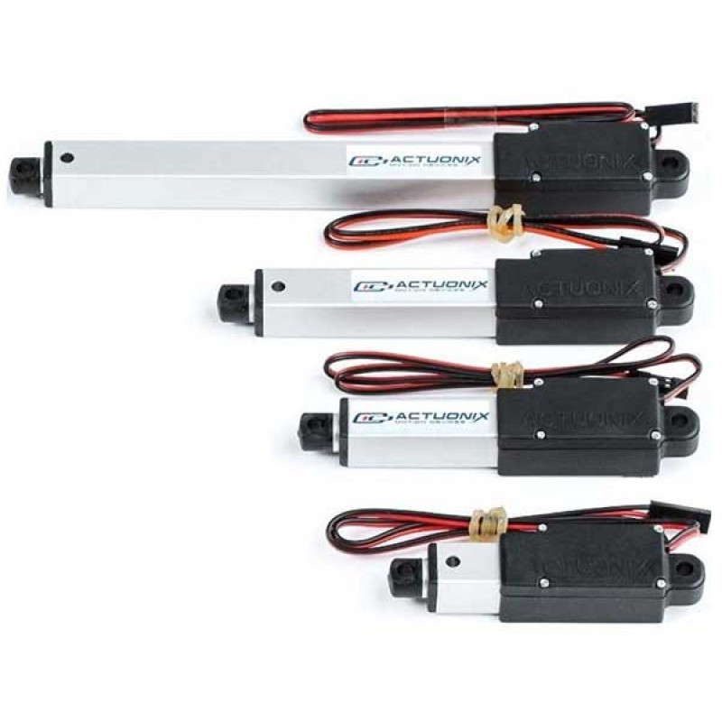
This type of actuator is the most prominent and common on the shelves due to its high level of customizability, simplicity and suitability for many uses. In the following section, we will cover the details of their control systems.
How to Use Relays to Control Linear Actuators
Controlling linear actuators is easy if you implement two SPDT relays. Depending on the number of outputs you need, you can choose from 2-channel, 4-channel and 8-channel boards. To explore and expand the range of functions of your actuator, you can combine the relays with motors or a motion control set-up.
Relays will regulate the direction of movement of your actuator by employing an electric current to stimulate a magnet that activates high-power currents. A microcontroller like Arduino can be used to power and run such a system. You can control linear actuator with Arduino to insert it into a mechanism that wouldn’t be normally manipulated by hand. This is allowed by remote control linear actuators, which can be upregulated by using a controller either with a long wire or wirelessly.
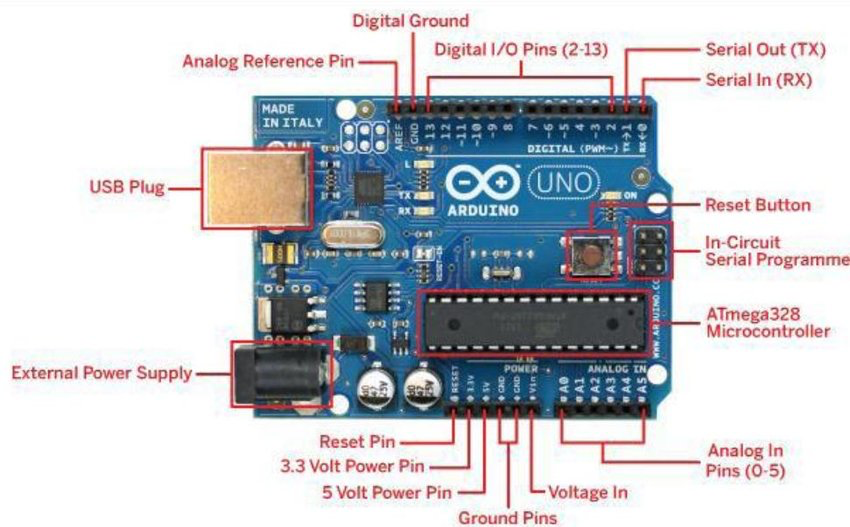
An Arduino microcontroller is a piece of programmable hardware that contains a number of microprocessors to execute the programs. It can administer the direction of the current, either directly by using a relay or via a feedback actuator. The direct method of control is easier to set up and is hence more widespread. It requires two relay boards to start, stop and redirect the current. An external source of power will be needed if you are using 4- or 8-channel board, since each separate relay consumes energy – normally, the power of the microcontroller will not be sufficient.
Setting Up a Board
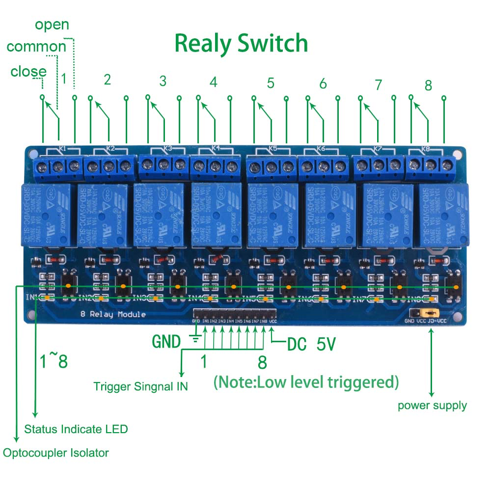
An SPTD relay has open, common and close connections on the relay side, and a GND pin, 8 IN pins and a VCC pin on the control side. To activate the relay, connect a power supply to the GND and VCC, and then join the required IN pin to Arduino. The IN pins have to be linked with GND pins.
The power will travel between the normally closed and common connections both if there is and there isn’t a connection with the IN pin. If it is connected to the GND pin, however, it will be between the normally open and common terminals. Keep in mind that the relay will only switch a limited number of times, otherwise causing destructive feedback.
The final element of the activation of linear actuator control is programming the Arduino board.
Conclusion
Linear actuators are common in all industries and have many different applications. For microlinear L12 actuators, there are several types, each varying in the type of control mechanism and most appropriate use. Controlling linear actuator with relay is possible through the use of a programmable Arduino board. It allows a sensitive regulation of the current and has a possibility for remote control.

Recommended For You
Why Is Katana the Core of Samurai Tradition
Most Inside Editorial Team
MostInside is a trusted publication helping people navigate real decisions across health, finance, career, home, relationships and technology since 2009. Straight to What Matters.


